29
October 2015
E
mbedded
C
omputing
icant role in a 40G backplane with 100G this
part will be much more critical. The imped-
ance discontinuities between the connector
and the backplane have a significant influence
on the properties of the whole transmission
channel (losses and cross-talk). If the discon-
tinuities are too large, the signal fed into the
transmission line is more sensitive to cross-
talk from adjacent differential signal traces.
When the losses and/or influence from cross-
talk are too great, the receiver cannot correctly
read the signal. With that, the bit error rate
gets increased.
To achieve the desired trace structure in a bare
board, new requirements for the quality of the
bare board are needed. Bare board material,
prepreg and core types, backdrilling, drilling
offset, etching and many other factors will play
an enormous role in 100G backplane design.
In addition to correctly defining those param-
eters, the quality and the tolerances of the bare
board manufacturing process are essential to
guarantee a reproducible result of 100G data
transfer. Even the smallest process deviation
during manufacture will influence the signal
properties and, in the worst case, not allow a
100G data transfer. This means it is essential
to very carefully choose a PCB manufacturing
partner who understands these needs and has
their processes carefully controlled. A close
partnership is needed to qualify those suppli-
ers and qualify the production technology and
processes.
The IEEE802.3bj 100G specification defines
parameter for the whole Ethernet chan-
nel, which is located between both trans-
ceiver chips. The transmission line of an
ATCA-backplane is just a part of the whole
transmission channel; both ATCA-boards are
located before and after the backplane within
the transmission channel. For that reason the
IEEE802.3bj parameter can’t be used one-to-
one for backplane validation. The IEEE802.3bj
parameter limits must be separated between
these three channel parts (both ATCA boards
and backplane). The PICMG 100G working
group is working on that, and companies like
Pentair are playing an active role defining this
new important standard.
n
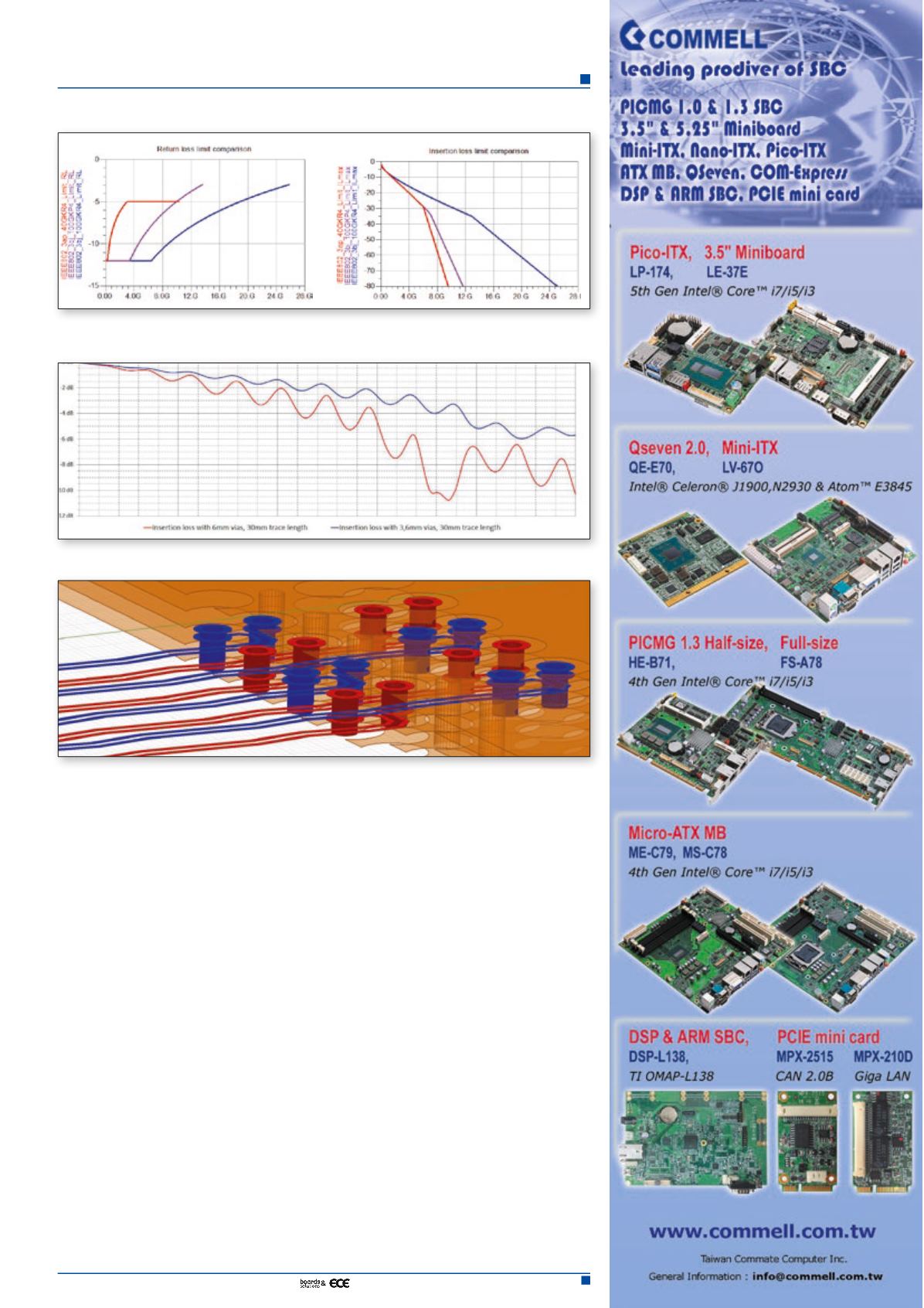
Figure 1 and 1.1. These graphs compare the thresholds for insertion loss (1A) and return loss (1B)
at 40G and both methods of 100G.
Figure 2. Comparison of insertion loss of a 30mm differential pair with 6mm and 3.6mm vias.
Figure 3. An example of vias and traces in a backplane


