May 2016
34
D
evelopment
T
ools
rithm components required for other modes
of operation (disabled, open loop, and encoder
calibration). We worked with the algorithm
engineer to identify which algorithm compo-
nents to model and decide whether to imple-
ment those components on the ARM or the
programmable logic on the SoC.
We elaborated the initial system model to
include the new algorithm components. To
enable system simulation we created lumped
parameter models of existing peripherals that
interact with themotor model. For example, we
had existing HDL code for the encoder periph-
eral that we planned to reuse in the deployed
design. The encoder peripheral reads a stream
of digital pulses at 50 MHz and translates them
into count signals read by the controller algo-
rithm at 25 kHz. If we directly modeled this
pulse stream, we would introduce 50 MHz
dynamics in the systemmodel and significantly
increase simulation time. Instead, we created
a lumped-parameter model of the encoder
which converts the ideal rotor position from
the motor model into the encoder counts sig-
nal seen by the algorithm components. Model-
ing at this level of fidelity enabled us to simulate
startup conditions required to test the Encoder
Calibration component as well as introduce
position quantization effects to test the Velocity
Control component while maintaining reason-
able simulation times.
We chose to implement algorithm compo-
nents on the ARM if they required rates of a
few kHz or less. The constraint of a few kHz
rates was set because we planned to run a
Linux operating system on the ARM. Algo-
rithm components requiring faster rates
would be implemented on the FPGA. We
wanted to implement algorithm components
on the ARM whenever possible because we
found that design iterations were faster on
the ARM than on the FPGA. It was easier to
target the algorithm to the ARM core because
it supported native floating-point math oper-
ations. Most FPGAs perform floating-point
math inefficiently, so targeting programma-
ble logic requires the additional step of con-
verting algorithms to fixed point. In addition,
we found the process of compiling C code for
the ARM was generally faster than compiling
HDL code for the FPGA. We used simulation
to determine whether algorithm components
could be executed at rates slow enough for the
ARM or if the FPGA was required. For exam-
ple, the algorithm engineer initially proposed
an encoder calibration routine that ran at 25
kHz, which would have to be implemented
on the FPGA. We used simulation to test
whether we could run the encoder calibration
component at 1 kHz, found that we could, and
decided to implement it on the ARM.
Once we had functionally correct models with
the desired component rates, we grouped all
components intended for C code generation
into an algorithm C model and all compo-
nents intended for HDL code generation into
an algorithm HDL model. We then iteratively
added implementation details to the mod-
els and generated code until we felt it would
fit within an acceptable amount of memory
and execute at the component rate. We used
Embedded Coder to generate C code from
the algorithm C model and generate a report
summarizing the calling interface and esti-
mated data memory usage. While reviewing
the report we realized that all the data types
were double-precision floating point. We
wanted the data that would interface to the
FPGA to be integer or fixed point and the
rest of the mathematics to be single-precision
floating point. We applied these data types
to the model, used simulation to verify the
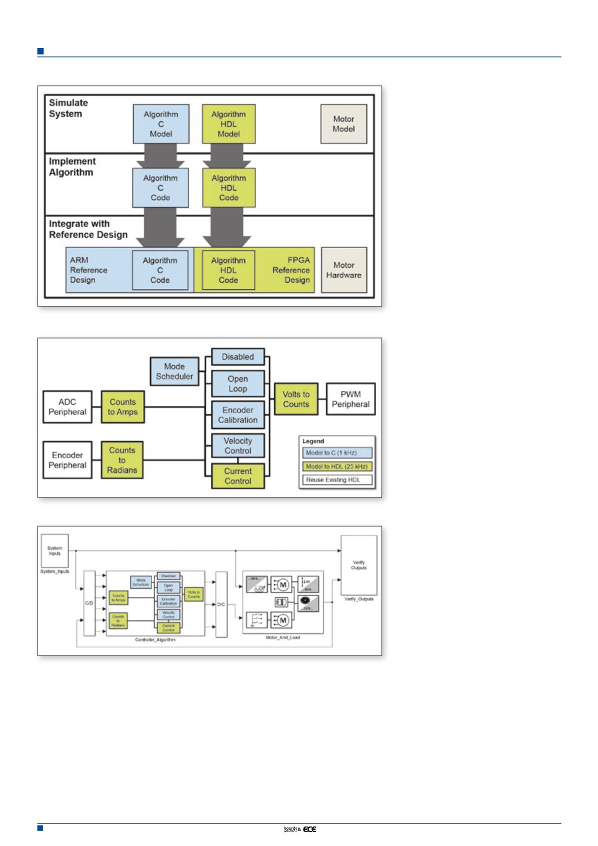
Figure 2. Workflow to develop and deploy a motor control algorithm to an SoC
Figure 3. Partitioning of algorithm components
Figure 4. System simulation model


