May 2016
35
D
evelopment
T
ools
behavior was still acceptable, and then gener-
ated the improved code. At this point we felt
confident that the code was suitable for imple-
mentation on the ARM.
We implemented the algorithmHDL model as
fixed point since fixed-point operations con-
sume fewer resources on FPGAs. To achieve
this, we worked with the algorithm engineer
to identify and bound key signal ranges in the
design (current, voltage, and velocity), then
used Fixed-Point Designer to define fixed-
point data types that would ensure calcula-
tions did not overflow. We used HDL Coder
to generate code and a summary report. We
reviewed the resource estimation section of
the report to identify math operations that
seemed unexpectedly large. For example, our
initial selection of word lengths resulted in
several multiplications of two 34-bit num-
bers, which we felt would needlessly consume
FPGA resources. We were able to identify this
issue in the resource utilization report, reduce
the precision in the model, use simulation to
verify functionality was still correct, and then
generate the improved code. We used Xilinx
Vivado Design Suite to synthesize the code
and verify that it met timing requirements.
Once we had a candidate algorithm imple-
mentation, we were ready to integrate it with
our reference design. We started by manually
integrating the generated C function with
our hand-coded ARM embedded project and
integrating the generated HDL entity with
our hand-coded Vivado project. However,
we realized that if we always performed the
integration manually, we would need to be
involved in every design iteration in the lab.
One of our goals in using this workflow was to
enable the algorithm engineer to automate the
integration and deployment process in the lab.
We used the HDL Coder Support Package
for Xilinx Zynq-7000 Platform to register
our hand-coded Vivado project as a refer-
ence design. We were then able to automate
integration of the generated algorithm HDL
code with our hand code, build a bitstream,
and download it to the FPGA. We used the
Embedded Coder Support Package for Xilinx
Zynq-7000 Platform to automate the integra-
tion of the generated algorithm C code with a
Linux operating system, build an executable,
download it to the ARM, and interact with
it from Simulink. The support packages pro-
vided the AXI interconnect that enabled com-
munication between algorithm components
in the ARM core and programmable logic.
During the initial system setup it was essential
for the algorithm and embedded engineers to
work together in the lab. As the embedded
engineers, we had to set up the deployment
configuration and work with the algorithm
engineer to verify basic functionality. Once
the system was set up, the algorithm engineer
could independently iterate on the design
using Simulink as the primary interface to
the SoC. The algorithm engineer tested the
deployed controller and determined that it
did not deliver the expected response. Com-
parison of the simulation and hardware results
showed that we had incorrectly calculated the
mapping of ADC count to current. The algo-
rithm engineer created additional tests to
better characterize the torque constant of the
motor and improve the correlation between
simulation and hardware.
The high correlation between the simulation
and hardware test results gave us confidence
that we could make design decisions at the
model level and reduce lab time even fur-
ther. For example, at one point the motor was
spinning in the lab but became uncontrolla-
ble under certain conditions. We theorized
that the issue was related to an overflow in the
fixed-point velocity calculation implemented
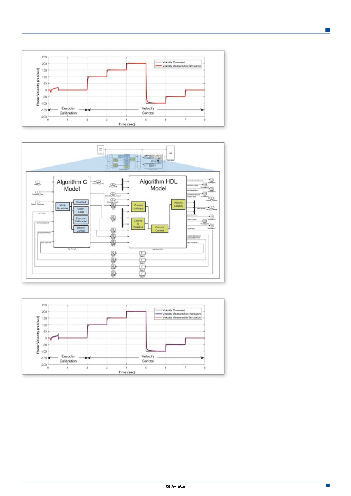
Figure 5. System simulation results for calibrating the encoder and stepping the velocity command
Figure 6. Controller algorithm models for C and HDL code generation
Figure 7. Comparison of simulation and hardware results


