May 2016
33
D
evelopment
T
ools
How modeling helps embedded
engineers develop applications for SoCs
By Mark Corless and Eric Cigan,
MathWorks
This article explains how modeling
helped a small team of algorithm
and embedded software engineers
design a motor control algorithm
and implement it on a programmable
system-on-chip (SoC).
Programmable SoCs such as Xilinx Zynq
SoCs and Altera SoC FPGAs, which com-
bine programmable logic and micropro-
cessor cores on the same chip, have given
design teams new platforms for algorithms
deployment in a wide range of applications,
including embedded vision, communications,
and control of motors and power electron-
ics. These design teams typically include two
categories of engineers: algorithm engineers,
responsible for conceptual development and
elaboration of math-based or rule-based algo-
rithms, and embedded engineers, responsible
for refining the algorithms and implementing
them in software or hardware on the embed-
ded device.
Algorithm engineers commonly use modeling
early in the development process to gain con-
fidence that their algorithms are functionally
correct for their application. Embedded engi-
neers, on the other hand, don’t always see the
benefits of modeling. However, when these
teams do not work closely together, the result
can be late error detection, causing project
delay; excessive resource use; or compromised
functionality due to inadequate design and
test iterations.
We set out to see whether modeling could
help both algorithm and embedded engi-
neers create a more efficient and collaborative
design process. We wanted to focus on mod-
eling algorithm components that we could
explore using simulation. We would use sim-
ulation to help us make partitioning decisions,
use simulation and code generation to bal-
ance functional behavior with implementa-
tion resources, and automate integration and
deployment of the generated code and hand
code to make more efficient use of lab time.
We proposed a workflow that would be a mix
of code generated from models and hand
code. Throughout the article we will refer to
the hand-coded portion of the design as the
reference design. We would begin with mod-
els provided by the algorithm developer and
iteratively elaborate the models by adding
implementation details. At each iteration we
would simulate system behavior to ensure the
functional correctness of the algorithm mod-
els, implement the algorithms with code gen-
eration to obtain code that behaved like the
model, and then automate integration with
our reference design to ensure a repeatable
process to get to hardware implementation.
For this case study we decided to design a
velocity controller for a permanent magnet
synchronous motor using a field-oriented
control (FOC) algorithm, and then to deploy
it to a Zynq-7000 All Programmable SoC
Intelligent Drives Kit II. We chose motor con-
trol because it is an application where algo-
rithm engineering and embedded engineers
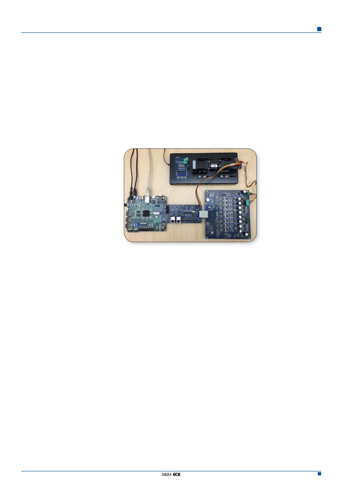
often need to work together. We chose the
Zynq Intelligent Drives Kit II because it was
readily available and offered the I/O support
we required. The Zynq Intelligent Drives Kit II
is a development platform used by engineers
who want to test motor control algorithms
running on a Zynq Z-7020 SoC device. Based
on the ZedBoard development board, the kit
includes an Analog Devices FMC motor con-
trol module and a 24V brushless DC motor
equipped with a 1,250 cycles/revolution
encoder. Because we wanted to test motor
control algorithms under a range of operat-
ing conditions, we used the Zynq Intelligent
Drives Kit II with an optional dynamometer
system.
After selecting the hardware platform, we
reviewed an initial system simulation model
provided by the algorithm engineer and iden-
tified additional algorithm components that
would be required for deployment to the SoC.
The model included a controller algorithm for
a motor based on data sheet parameters. This
algorithm consisted of an outer velocity control
loop regulating an inner current control loop
using FOC. Although this model captured the
core mathematics of the controller, it did not
take into consideration the effects of peripher-
als (such as ADC, encoder, and PWM) or algo-
Figure 1. Zynq Intelligent
Drives Kit II with optional
dynamometer system
(from Avnet Electronics
Marketing)


