M
OTOR
C
ONTROL
etc. This is true for both analog/trapezoidal
drives and digital/sine drives. These devices
have protection built in the hardware. The
DSP-based solution also can have soft limits
set that interface with the motor control system
with parameters set by the GUI. The control
and power stages for these motor controllers
are available in compact form, such as a hybrid
or module, which can be integrated into larger
systems.
The controllers and supporting electronics
typically are mounted on or near the motor.
The motor system will also include a DC bus
capacitor to reduce ripple and possibly EMI
filters to reduce noise on the system bus. Con-
sideration must also be given to dissipate
motor energy Back Electro Motive Force
(BEMF) that is generated when the motor
shuts down. A large amount of mechanical en-
ergy is converted back into electrical energy,
and this must be considered in the overall sys-
tem design with implementation of a braking
resistor or other method to store or dissipate
this energy such as capacitor networks or bat-
teries. For higher voltage systems, the bus ca-
pacitor should be of good quality and low
equivalent series resistance (ESR) to reduce
bus ripple. This capacitor should be located
close to the controller to reduce resistance.
Most electronic systems must meet electro
magnetic interference (EMI) standards for sys-
tem compatibility. This ensures that the elec-
tronics will not interfere with or be interfered
by other devices. Standards govern the devices
radiated radio frequency (RF) emissions as
well as susceptibility. There are commercial
and military standards such as MIL-STD-461
that is typically used for US military and
avionic systems and less rigorous FCC stan-
dards in the US. Europe issued an EMC Direc-
tive (89/336/EC) in the 1980s and other coun-
tries have similar standards. A good motor
and controller system will be designed to these
standards and have an EMI filter integrated
into the system. This can be found located in
a box level motor control solution at or near
the motor. In a larger system, an overall solution
is used. The object is to reduce the cost of
qualifying the system as well as meeting control
system size and weight constraints.
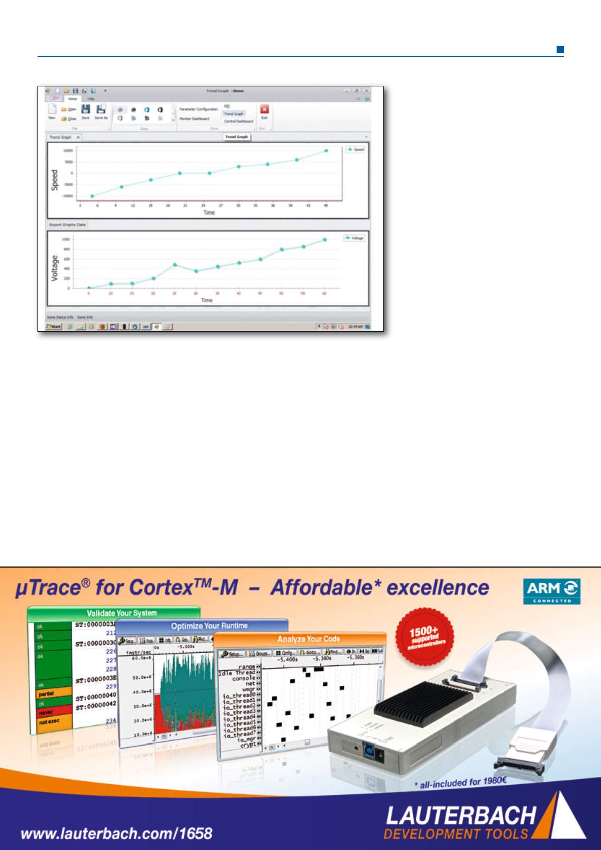
The DSP-based devices feature graphical user
interfaces (GUI) that can operate the motor
and be used to optimize performance. Complex
calculations are carried out for the control
loops. The processor memory also enables
users to save motor data, such as voltage and
current, which may then be viewed through a
data logger for analysis. One can analyze start
up issues by reviewing motor current, voltage,
as well as optimize the bandwidth to reduce
torque ripple to optimize motor performance.
These types of tools have become the industry
standard, and are included with the purchase
of the motor controller.
Modern motor control products will continue
to meet the growing demand for automation
and motor control, as complex systems can
now be supported with compact solutions.
These designs provide all the processing power
required for precise and efficient motor control,
and can easily be integrated into box and
system level solutions.
Screen shot of a data logger


